SIMATIC TIA Portal Structured Programming
The Programming Process
Planning an Automation Project
Before beginning programming, a detailed planning is required. The typical planning steps are:
- Divide the process into tasks
- Describe each task area
- Define the safety requirements
- Describe the operator displays and controls
- Create configuration diagrams
Describing each task can be done via flowcharts and then assembling the various flowcharts into a unified one for the process.
The safety requirements description is done at the same time when describing other equipment requirements. Safety requirements must consider:
- Functional Safety
- Electrical Safety
- Fire Safety
- Environmental Safety
Safety requirements depend upon various factors for which a risk assessment is performed. The design of the safety system can incorporate localized safety devices and devices and systems which are independent from the PLC
Following Standards and Guidelines
IEC 61131
Is a multi-part standard that manufactures adhere in order to make it easier for users to program, operate and maintain systems:
- Part 1: General Information
- Part 2: Equipment Requirements and Tests
- Part 3: Programming Languages
- Part 4: User Guidelines
- Part 5: Communications
- Part 6: Functional Safety
- Part 7 - 10: Additional Technical Topics
Data Types
Data values are stored in PLC as 1's and 0's. Each 1 or 0 is referred as a bit. There are many data types, and the number of bits involve typically range in length from 1 bit 64 bit:
- Boolean (BOOL)
- Bit String
- Signed Integer
- Unsigned Integer
- Real Number
- Time
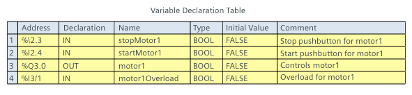
Variables
PLC programs work with data stored in memory locations, referred to as addresses, and instructions in the program must identify associated addresses. This is done through variables
A variable can be displayed as an absolute memory address. This type of variable is preceded by %.
Symbolic variables, also called tags, have names and use alphanumeric characters, but are intended to be representative of a function being performed. Symbolic variables can be global variables (enclosed in quotations " ") or local variables (preceded by #).
Variables must be declared in a table, or data block, and should use a style guide such as:
- Unique
- camelCasing Notation
- 24 Characters (max)
- No Special Language Characters
- No Spaces or Separators
- Meaningful
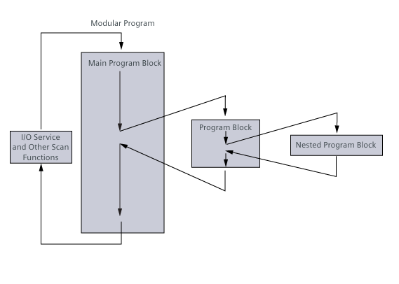
Program Blocks and Modular Programming
A program block contains a portion of a program. Use of program blocks allows for modular programming, also called structured programming.
A modular program can have multiple program blocks and, if needed, a program block can be used multiple times in a single PLC scan cycle.
Another feature of a modular program is program nesting. Nesting occurs when the main program block calls another program block, which calls another program block and so on.
PLC Programming Languages
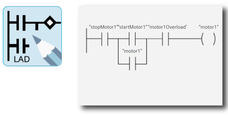
Ladder Diagram (LAD)
Is a graphical programming language originally based on the control circuit diagrams. LAD is easy to use for basic control applications, but no so good for complex algorithms
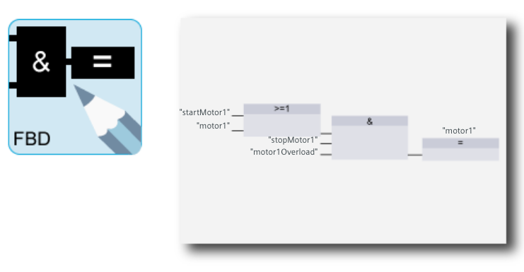
Function Block Diagram (FBD)
Is similar to LAD, however, rather than contact logic, it uses boolean logic instructions with similar functionality to the logic gates of a digital logic circuit. Easy to use for basic algorithms, but time consuming for complex control algorithms
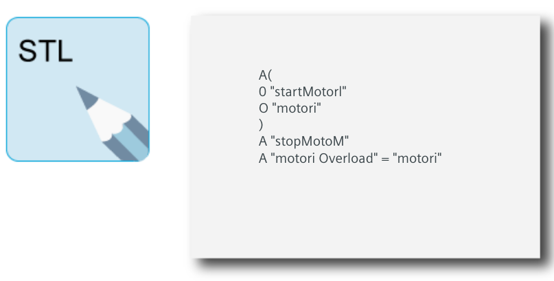
Statement List (STL)
Is a text-based language with same capabilities as LAD and FBD. Its a low-level language similar to assembly. Instead of using graphical symbols, STLS uses programming statements that are listed and solved from top to bottom. It may have some performance advantages but it's cumbersome for complex algorithms
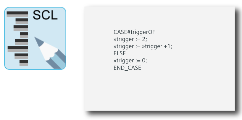
Structured Control Language (SCL)
Is a high-level, PASCAL-based programming language. Is generally considered the best PLC programming language to use for complex algorithms and processing of complex data structures. SCL has common program control operations such as IF-THEN-ELSE, CASE, REPEAT-UNTIL, GOTO and RETURN. In addition, SCL has control operations such as timers and counter that allow it to be used for control applications
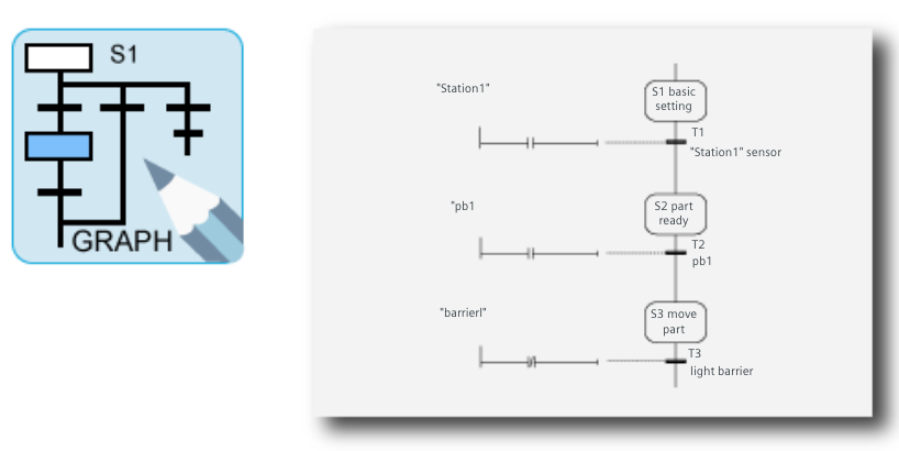
GRAPH
Is a language designed for the development of sequential control programs. A sequential control program is divided into individual steps which are executed step by step. Execution of the next step in the series is controlled by transitions and step enabling conditions.
PLC Programming Concepts
TIA Portal
Siemens Totally Integrated Automation Portal software is used in all phases of an automation system design, operation and maintenance
STEP 7
For Siemens PLCs, the following engineering software is used:
- S7-300 and S7-400 PLCs require STEP 7 Professional (TIA Portal) or STEP 7 Professional (Solo)
- S7-1200 PLCs require STEP 7 Basic (TIA Portal) or STEP 7 Professional (TIA Portal)
- S7-1500 PLCs require STEP 7 Professional (TIA Portal)
STEP 7 Basic support LAD, FBD and SCL.
STEP 7 Professional includes support for LAD, FBD, SCL, STL also known as Instructions Lists (IL) and SFC included as S7-GRAPH. STEP 7 Professional also includes S7-PLCsim software, which simulates a controller for functional testing of user blocks and programs
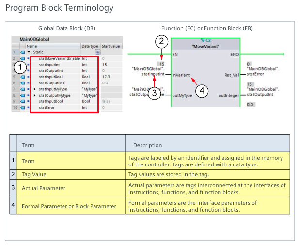
Program Blocks
An S7 PLC program can include data blocks (DBs) and three types of program blocks:
- Organization Blocks (OBs)
- Functions Blocks (FBs)
- Functions (FCs)